


পণ্য পরামর্শ
আপনার ইমেল ঠিকানা প্রকাশ করা হবে না. প্রয়োজনীয় ক্ষেত্রগুলি চিহ্নিত করা হয়েছে *


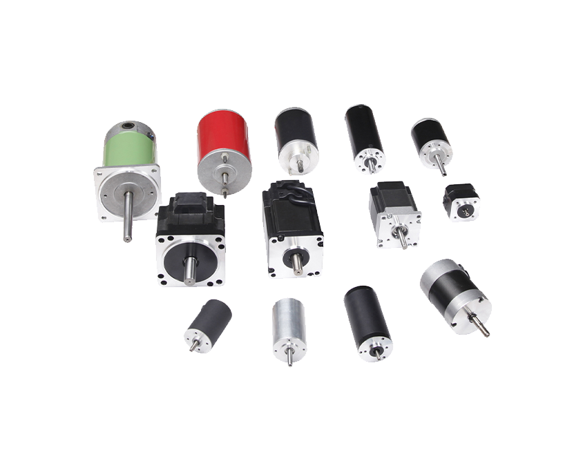
Solar tracking systems are designed to orient photovoltaic panels or concentrating solar collectors toward the sun throughout the day, maximizing the amount of solar radiation captured. At the mechanical heart of every solar tracker is a gear motor — the actuator responsible for converting electrical energy into the precise, controlled rotational movement that repositions the panels. Without a reliable drive motor with the right gear reduction, even the most sophisticated tracking algorithm produces no real-world movement.
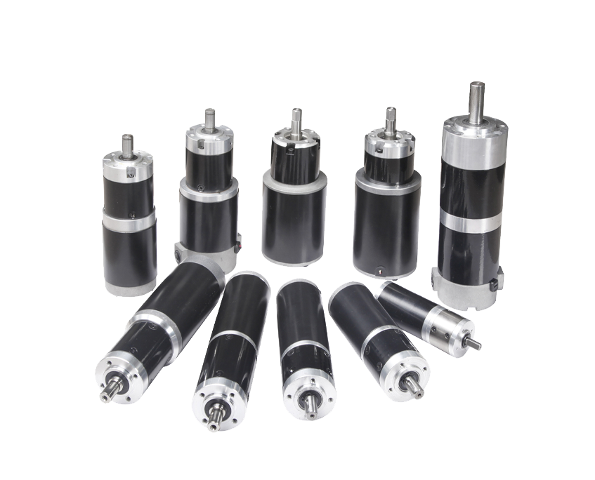
A Gear Motors for Solar Tracking Systems combines an electric motor with an integrated gearbox, reducing the motor's high-speed, low-torque output into the low-speed, high-torque output needed to rotate large, wind-loaded panel arrays. The gearbox also provides a mechanical advantage that allows a relatively small motor to move a structure weighing hundreds of kilograms with accuracy measured in fractions of a degree. This combination of precision, torque, and self-locking capability under load makes gear motors indispensable in both single-axis and dual-axis solar tracker designs.
Not all gear motors are suitable for solar tracking applications. The choice of motor and gearbox type profoundly affects tracking accuracy, power consumption, maintenance requirements, and long-term reliability. Each configuration has distinct strengths depending on the scale and design of the solar installation.
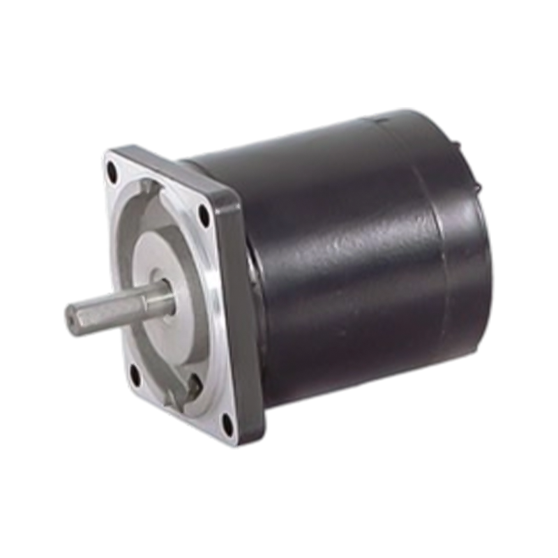
Worm gear motors are among the most widely used drive solutions in solar tracking systems, particularly for single-axis trackers in utility-scale solar farms. A worm gear consists of a helical screw (the worm) meshing with a toothed wheel (the worm wheel), producing very high gear reduction ratios — typically ranging from 10:1 to 100:1 or more — in a compact form factor. This high reduction ratio delivers the substantial torque needed to rotate large panel rows while keeping motor size and energy consumption low.
One of the most valuable characteristics of worm gear motors in solar applications is their inherent self-locking property. When the motor is not energized, the geometry of the worm mesh prevents back-driving — meaning wind loads acting on the panel surface cannot rotate the drive mechanism backward. This passive holding capability eliminates the need for separate braking systems in many designs and is a critical safety feature in high-wind environments.
Helical gear motors offer higher mechanical efficiency than worm gears — typically 85 to 96 percent versus 50 to 90 percent for worm drives — making them better suited for applications where continuous movement or frequent repositioning is required, such as high-precision dual-axis trackers or concentrating photovoltaic (CPV) systems. The angled tooth profile of helical gears allows multiple teeth to engage simultaneously, producing smoother, quieter operation and distributing load more evenly across the gear face.
The trade-off is that helical gear motors are not self-locking, requiring either a separate electromechanical brake or a secondary holding mechanism when the motor is at rest. In solar tracking applications, this is typically addressed through brake-equipped motors or by incorporating a secondary worm stage into a helical-worm combination gearbox, which delivers both efficiency and holding capability.
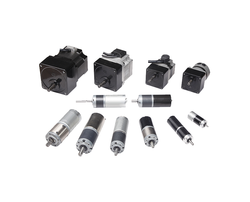
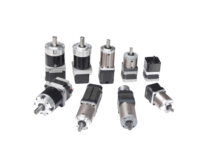
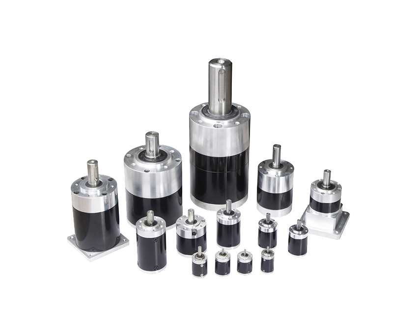
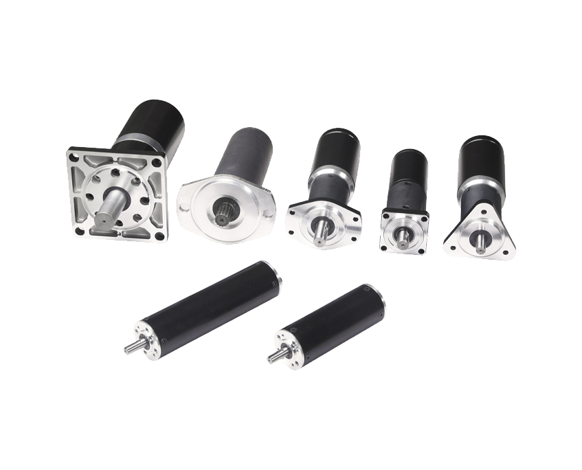
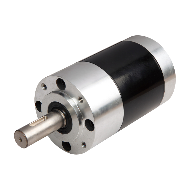
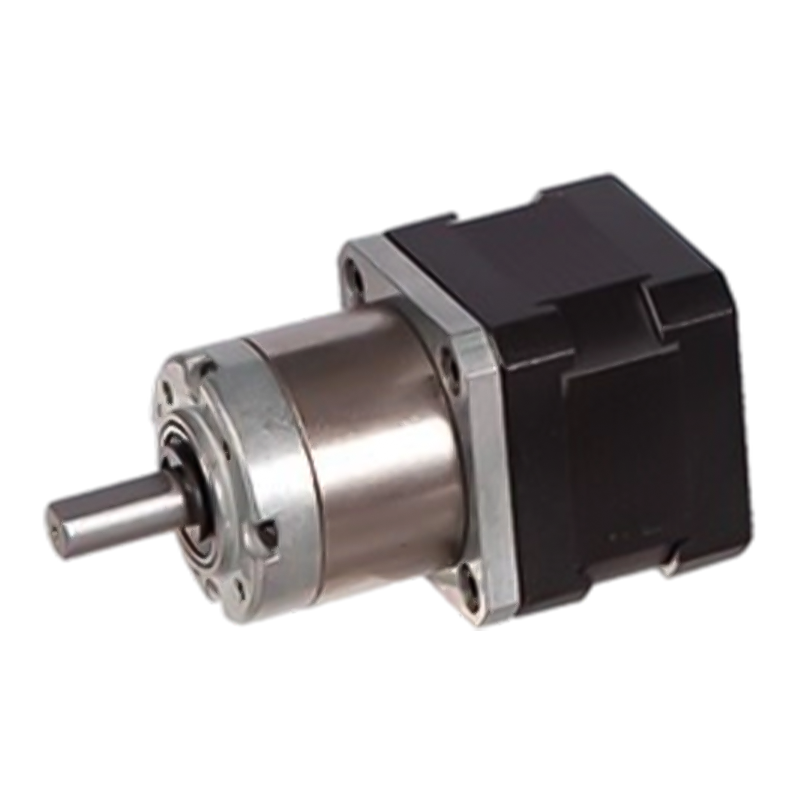
Planetary gear motors are compact, highly efficient, and capable of achieving very high torque-to-size ratios. In a planetary gearbox, a central sun gear drives multiple planet gears that rotate around it, all contained within an outer ring gear. This coaxial arrangement distributes the load across multiple contact points simultaneously, resulting in excellent torque capacity and long service life even under continuous or cyclic loading conditions.
Planetary gear motors are commonly used in dual-axis solar trackers and in high-accuracy CPV trackers where pointing accuracy within ±0.1 degrees is essential. Their high efficiency makes them particularly well-suited for battery-powered or off-grid solar tracking systems where minimizing drive energy consumption is critical. Like helical gears, planetary gearboxes are not inherently self-locking and typically require integrated braking when used as solar tracker drive motors.
Slew drives are a specialized category of worm-driven gear motors designed specifically for the demands of solar tracking. A slew drive integrates a worm gear set, a slewing ring bearing, and a housing into a single, sealed unit that can simultaneously support structural loads and provide rotational drive. This all-in-one design simplifies installation, reduces the number of mechanical components in the tracker structure, and provides excellent resistance to axial, radial, and moment loads from wind and panel weight.
Slew drives are particularly popular in dual-axis solar trackers, concentrated solar power (CSP) dish systems, and heliostat fields where each individual mirror or panel assembly requires its own independent drive unit. The self-locking nature of the worm drive within the slew drive unit means the tracker holds its position without power, a feature that is both energy-efficient and mechanically safe during grid outages or control system failures.
Choosing the right gear motor for a solar tracking application requires careful evaluation of several interdependent parameters. Selecting a motor based on torque alone — without considering duty cycle, backlash, ingress protection, or operating temperature range — frequently leads to premature failure or inadequate tracking performance.
|
Specification |
Typical Range / Value |
Why It Matters |
|
Output Torque |
50 Nm – 50,000 Nm+ |
Must overcome panel weight, wind load, and friction at worst-case conditions |
|
Output Speed |
0.01 – 5 RPM |
Determines how quickly the tracker repositions; most solar trackers need very slow, precise movement |
|
Gear Ratio |
20:1 – 3,000:1 |
Higher ratio = more torque and slower speed; affects self-locking behavior |
|
Backlash |
< 0.1° – 1° |
Low backlash is critical for high-precision CPV and CSP systems; less critical for flat-panel PV |
|
Ingress Protection (IP Rating) |
IP55 minimum; IP67 preferred |
Outdoor exposure to rain, dust, humidity, and condensation requires robust sealing |
|
Operating Temperature |
-40°C to +85°C |
Must function reliably from desert heat to sub-zero winter conditions |
|
Duty Cycle |
Intermittent (S3/S4) to continuous (S1) |
Solar trackers typically operate in short repositioning cycles throughout the day |
|
Input Voltage |
12V / 24V DC or 110V / 230V AC |
Must match available power supply; DC motors preferred for off-grid systems |
|
Self-Locking Capability |
Yes (worm) / No (helical, planetary) |
Determines whether a separate braking mechanism is required to hold position |
Calculating the torque required from a solar tracker gear motor is one of the most important steps in system design. Undersizing the drive torque leads to stalling under load, missed tracking positions, and accelerated motor wear. Oversizing wastes cost and energy. The total required torque is the sum of several contributing forces acting on the rotating panel structure.
Gravitational torque:The torque produced by the weight of the panel array acting through its center of mass relative to the pivot axis. For a well-balanced tracker, this component can be minimized by careful panel mounting design, but it is rarely zero in practice.
Wind load torque:The torque produced by aerodynamic drag and lift forces acting on the panel surface. This is typically the dominant torque component, especially in open-field utility installations, and must be calculated at the maximum design wind speed for the site — often 120 to 200 km/h for survival load cases.
Friction torque:The torque required to overcome static and dynamic friction in the bearings, pivots, and drive train. Friction increases in cold conditions as lubricant viscosity rises, which is why low-temperature lubrication specifications matter greatly in northern climates.
Inertia torque:The torque required to accelerate the panel structure from rest during repositioning. While solar trackers move slowly, large panel arrays can have significant rotational inertia that affects the required peak motor torque at startup.
Safety factor:All calculated torques are multiplied by a safety factor — typically 1.5 to 2.0 — to account for worst-case combinations of simultaneous loading, component wear over time, and manufacturing tolerances in both the drive and the structure.
Solar tracking systems are broadly categorized into single-axis and dual-axis configurations, and each imposes distinct requirements on the gear motor drive system. Understanding these differences is essential when specifying drive motors for a new installation or retrofitting an existing tracker.
Single-axis trackers rotate on one axis — typically oriented north-south — to follow the sun's east-to-west daily arc. A single drive motor rotates a long torque tube that simultaneously repositions a row of panels, sometimes spanning 50 to 100 meters in utility-scale installations. This row drive configuration places very high torque demands on the motor but requires relatively low angular precision — typically ±1 degree is sufficient for flat-panel PV systems. Worm gear motors and slew drives are the dominant choices for single-axis applications because their self-locking behavior holds the row in position during wind events without power consumption.
Dual-axis trackers add a second rotation axis — typically tilting north-south in addition to east-west rotation — allowing the panel to be pointed directly at the sun at any time of year, including seasonal elevation changes. Each axis requires its own independent gear motor, so a single dual-axis tracker unit contains two drive motors. The azimuth (horizontal rotation) axis typically carries the highest torque demand, while the elevation (tilt) axis requires less torque but often greater precision. CPV and CSP dish systems require pointing accuracy of ±0.1 degrees or better, making low-backlash planetary or helical gear motors the preferred choice for the elevation drive despite their higher cost.

Solar tracker gear motors operate outdoors, continuously exposed to weather, temperature extremes, UV radiation, dust, humidity, and in coastal installations, salt spray. A motor that performs perfectly in a controlled environment may fail within months if its sealing, lubrication, and material specifications are inadequate for the deployment site. Specifying environmental durability correctly is as important as getting the torque and speed right.
IP Rating:The Ingress Protection rating defines the motor's resistance to solid particles and liquid ingress. Solar tracker motors should carry a minimum rating of IP55 (protected against dust and water jets), with IP65 or IP67 preferred for installations in high-rainfall or dusty desert environments. IP67-rated motors can withstand temporary immersion, providing additional margin against flooding during extreme weather.
Corrosion-resistant materials and coatings:Housings made from aluminum alloy, stainless steel, or powder-coated ductile iron with appropriate surface treatment are essential for longevity. In marine environments, additional corrosion protection — such as marine-grade anodizing or specialized epoxy coatings — is required to resist salt-induced oxidation.
Wide-temperature lubrication:Standard gear lubricants thicken dramatically in cold temperatures, increasing friction and startup torque requirements. Solar tracker motors intended for operation below -10°C require specially formulated synthetic lubricants that remain fluid across the full operating range, typically rated from -40°C to +120°C.
UV and ozone-resistant seals:Rubber seals and cable entry gaskets exposed to prolonged UV radiation degrade and crack over time, compromising the motor's IP rating. EPDM or silicone seals are far more UV-resistant than standard NBR rubber and should be specified for outdoor solar applications.
Thermal management:In desert environments, ambient temperatures can exceed 50°C. The motor's thermal class rating — typically Class F (155°C) or Class H (180°C) — must provide adequate margin above the combined ambient and self-heating temperature to prevent insulation degradation and premature winding failure.
Modern solar tracker gear motors are rarely standalone mechanical components — they are tightly integrated with electronic control systems, position feedback devices, and communication networks. The interface between the gear motor and the tracker control system determines how accurately and reliably the system tracks the sun in real-world conditions.
Position feedback is provided by encoders, resolvers, or potentiometers mounted on the motor output shaft or integrated into the slew drive. Absolute encoders are preferred over incremental encoders for solar tracking because they retain position information even after a power outage — the controller knows exactly where the tracker is pointing when power is restored, without requiring a homing sequence. This is particularly important in utility-scale installations with hundreds of tracker rows, where simultaneous homing sequences would cause large, uncontrolled current spikes.
Many solar tracker applications use DC gear motors driven by pulse-width modulation (PWM) controllers, which allow smooth speed control and soft-start capability that reduces mechanical stress during repositioning. Brushless DC (BLDC) gear motors are increasingly popular for high-reliability installations because they eliminate the brush wear mechanism that limits the service life of traditional brushed DC motors, potentially extending maintenance-free operation to 20,000 hours or more — matching the long-term investment horizon of utility solar installations.
A common concern in solar tracking system design is whether the energy consumed by the drive motors offsets the energy gain from tracking. In practice, well-designed solar tracker gear motors consume a small fraction of the additional energy generated by tracking — but this must be verified through proper specification rather than assumed.
Single-axis trackers typically generate 20 to 30 percent more energy annually than fixed-tilt systems at mid-latitudes, while dual-axis trackers can deliver 35 to 45 percent gains. The gear motors driving these systems operate intermittently — typically for a few seconds every few minutes — and consume energy only during repositioning movements. The cumulative daily energy consumption of a gear motor for a single-axis tracker is often less than 10 watt-hours, compared to an energy gain of hundreds of watt-hours per day from the additional solar capture. Choosing motors with high gearbox efficiency, appropriate for the actual duty cycle, and matched to the actual load torque — rather than significantly oversized — keeps parasitic drive energy consumption to a minimum.
Solar installations are typically designed for 20 to 30-year operational lifespans, creating demanding long-term reliability expectations for every mechanical component including the gear motor drives. Understanding realistic service life expectations and maintenance requirements helps project developers budget accurately and avoid costly mid-project drivetrain replacements.
Lubrication service:Most sealed gear motors for solar applications use lifetime-lubricated gearboxes that require no routine oil changes under normal operating conditions. However, in extreme environments — very high temperatures, heavy contamination, or subzero winters — periodic inspection and re-lubrication every 5 to 10 years is recommended to prevent lubricant degradation.
Seal inspection:The IP rating seals should be inspected annually for cracking, hardening, or distortion — particularly at cable entry points and housing joints — and replaced if deterioration is found. Failed seals are the most common entry path for moisture and contaminants that cause internal corrosion and bearing damage.
Bearing service life:Industrial-grade sealed bearings in properly specified solar tracker motors have design lives of L10 ratings exceeding 20,000 to 30,000 hours under nominal loads. Overloading — typically from wind events that exceed the design load — is the primary cause of premature bearing failure and can be mitigated by incorporating stow position control that moves panels horizontal during high-wind conditions.
Brush replacement (brushed DC motors):If brushed DC motors are used, brush wear is a predictable maintenance item typically requiring replacement every 3,000 to 8,000 operating hours depending on load and speed. In solar tracking applications with intermittent duty cycles, this may translate to 5 to 15 years between brush replacements.
Fastener and mounting inspection:Vibration from wind loading can loosen mounting bolts over time. Annual torque checks on motor mounting hardware and drive couplings are a simple preventive measure that avoids the much larger consequence of a drive unit becoming loose or misaligned within the tracker structure.
Selecting the most appropriate gear motor type for a solar tracking application depends on balancing precision requirements, torque capacity, efficiency, cost, and long-term reliability. The following comparison table summarizes the key trade-offs between the four main gear motor types used in solar tracking systems.
|
Gear Motor Type |
Efficiency |
Self-Locking |
Backlash |
Best Application |
Relative Cost |
|
Worm Gear Motor |
50–90% |
Yes |
Moderate |
Single-axis PV trackers |
Low–Medium |
|
Helical Gear Motor |
85–96% |
No |
Low–Moderate |
High-efficiency dual-axis trackers |
Medium |
|
Planetary Gear Motor |
90–97% |
No |
Very Low |
CPV / high-precision dual-axis |
High |
|
Slew Drive |
50–85% |
Yes |
Moderate |
Dual-axis trackers, CSP dishes, heliostats |
Medium–High |
Correctly specifying a gear motor for a solar tracking project requires close collaboration between mechanical, electrical, and civil engineers to ensure that the drive solution accounts for site-specific loading conditions, control system architecture, maintenance access constraints, and long-term cost of ownership — not just the initial purchase price.
Always calculate the required torque under worst-case wind load conditions at the specific site, using local wind speed data and the actual panel array dimensions — never rely on generic estimates from tracker datasheet examples.
Request motor manufacturers to provide tested IP certification documentation, not just rated values, and verify that the certification covers the specific cable gland entries and mounting orientations used in your installation.
Specify the lubrication type and temperature range explicitly in the purchase specification, particularly for cold-climate installations where standard gear oil can gel at startup and cause mechanical damage or motor overload.
For utility-scale projects, require manufacturers to provide L10 bearing life calculations based on the actual applied loads — not generic catalog ratings — and request field reference data from comparable solar installations with equivalent operating histories.
Evaluate total cost of ownership over the project's design life rather than first cost alone: a higher-quality gear motor that eliminates one unplanned field service visit over 25 years typically delivers significantly lower lifetime cost than the cheapest available option requiring periodic replacement.
Confirm spare parts availability and the manufacturer's commitment to long-term product support before finalizing the selection — a motor that is discontinued five years into a 25-year project creates expensive retrofitting challenges in the field.
আপনার ইমেল ঠিকানা প্রকাশ করা হবে না. প্রয়োজনীয় ক্ষেত্রগুলি চিহ্নিত করা হয়েছে *
কপিরাইট © Zhejiang Dongzheng মোটর কোং, লিমিটেড সর্বস্বত্ব সংরক্ষিত.
 ডিসি গিয়ার মোটর নির্মাতারা